Email: sales@unikelly.com WhatsApp: +86 19108462246
Email: sales@unikelly.com WhatsApp: +86 19108462246
To measure a Kelly bar accurately, check its outer diameter, individual section lengths, overall extended and retracted lengths, section overlap, connection dimensions, and drive key or locking geometry. These measurements help determine whether a Kelly bar can fit a rotary drilling rig or replace an existing unit. For accurate replacement or customization, measurements should be combined with the rig model, operating torque, drilling depth, and original technical drawings whenever available.
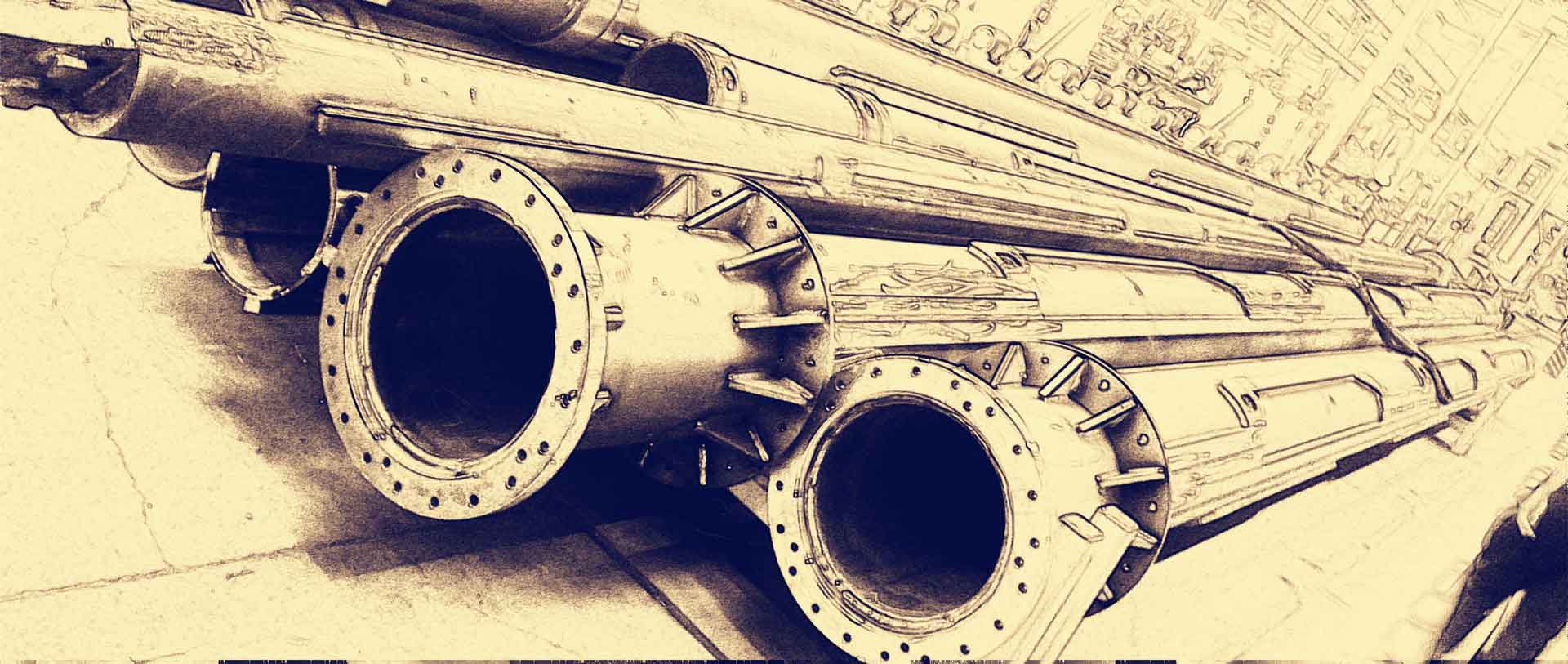
A Kelly bar is a telescopic component designed to transmit torque and crowd force from a rotary drilling rig to the drilling tool. Its dimensions must match the rig's rotary drive, Kelly bar guide, and operating requirements.
Incorrect measurements can lead to several problems:
The Kelly bar may not fit the rotary drive.
The telescopic sections may not slide correctly.
The locking or drive keys may not engage properly.
The available drilling depth may be insufficient.
The Kelly bar may interfere with the rig's mast or lifting system.
The replacement unit may have an unsuitable weight or structural configuration.
For this reason, measuring a Kelly bar involves more than checking the outside diameter and total length.
A complete dimensional assessment should cover the main telescopic sections, connection interfaces, and torque-transmission components.
The first measurement is the diameter of the telescopic steel sections.
For a standard tubular Kelly bar, diameter measurements should be taken at the specified reference locations on the steel tube, avoiding weld seams, local reinforcement, and worn or deformed areas.
When measuring an existing Kelly bar, record:
Outer diameter of the outermost section.
Outer diameter of each accessible inner section.
Relevant internal dimensions if required by the replacement design.
Wall thickness, where accessible or available from the original drawing.
A calibrated outside micrometer or large-diameter measuring tool can be used for more accurate measurements.
Do not assume that every section has the same diameter. Telescopic Kelly bars use progressively smaller sections that fit inside one another.
For customized replacement, the supplier may also need the tube dimensions and the required clearance between telescopic sections.
The individual section length is essential for determining the telescopic configuration and drilling depth.
A Kelly bar generally contains multiple nested steel sections. Each section has its own length, and the total assembly length depends on how these sections overlap.
Record the following information:
| Measurement | Description |
| Outer Section Length | Length of the largest steel tube |
| Second Section Length | Length of the second telescopic tube |
| Intermediate Section Lengths | Lengths of the remaining inner tubes |
| Inner Section Length | Length of the smallest telescopic tube |
For example, a five-section Kelly bar may have a configuration described as 5 × 15 m. This indicates five sections with nominal lengths of approximately 15 meters each.
However, the actual drilling depth is not simply the sum of these lengths. Section overlap, the telescopic stroke, the rig configuration, and the drilling tool connection all influence the effective drilling depth.
When possible, measure each section separately and record its position in the telescopic assembly.
Apart from individual section lengths, the overall assembly dimensions are important for installation and compatibility.
Two measurements should be distinguished:
Retracted length: The overall length of the Kelly bar when its telescopic sections are fully retracted.
Extended length: The overall length when the telescopic sections are fully extended to their specified operating position.
These measurements help determine whether the Kelly bar can operate within the available mast height and lifting stroke of the drilling rig.
It is important to measure from clearly defined reference points. For example, the distance from the upper connection reference surface to the lower tool connection reference surface should be recorded consistently.
If the Kelly bar is still installed on a rig, measurements should only be taken under safe maintenance conditions, with the equipment secured and all relevant safety procedures followed.
Section overlap is an important structural dimension that is sometimes overlooked during Kelly bar replacement.
Because the sections slide inside one another, a certain overlap must be maintained when the Kelly bar is extended. This overlap helps support the telescopic structure and allows torque and axial forces to be transmitted through the assembly.
When measuring an existing Kelly bar, record:
The overlap between adjacent sections.
The available extension stroke of each section.
The position of mechanical stops or locking points.
The relative position of drive keys and locking components.
Insufficient overlap can affect structural stability and load transmission. The correct overlap should be determined by the original design or engineering requirements rather than estimated from appearance alone.
The torque-transmission components are among the most important dimensions of a Kelly bar.
For a Friction Kelly Bar, pay attention to the drive keys and their arrangement on each telescopic section. Their dimensions and positioning influence torque transfer and sliding performance.
For an Interlocking Kelly Bar, the mechanical locking structure must be measured carefully. The locking geometry, engagement position, and corresponding dimensions must match the intended design.
Record:
Number of drive keys or locking features.
Key width and height.
Key length.
Key spacing and position.
Locking groove dimensions, where applicable.
Wear condition of the contact surfaces.
A replacement Kelly bar with the correct tube diameter but an incorrect key configuration may not function properly.
Therefore, key geometry should be treated as a critical compatibility requirement, not a secondary detail.
The connection interfaces determine how the Kelly bar attaches to the rotary drilling rig and drilling tool.
The upper connection must match the rig's rotary drive arrangement. The lower connection must be compatible with the drilling tool or adapter.
Depending on the design, relevant dimensions may include:
Connection diameter.
Bolt-hole diameter and spacing.
Connection flange dimensions.
Thread specifications, if applicable.
Pin or locking arrangement.
Connection length and reference position.
Adapter geometry.
Do not rely on visual similarity when checking connections. Two Kelly bars may look almost identical but have different connection dimensions.
When possible, provide the original connection drawing or clear photographs with a measuring scale.
Before requesting a replacement or customized Kelly bar, organize the measurements into a technical record.
| Item | Information to Record |
| Rig Brand and Model | Exact rotary drilling rig model |
| Kelly Bar Type | Friction or Interlocking |
| Number of Sections | 3, 4, 5, 6, etc. |
| Outer Diameter | Diameter of the outer section |
| Inner Section Diameters | Dimensions of each telescopic section |
| Individual Section Lengths | Length of every section |
| Extended Length | Fully extended assembly length |
| Retracted Length | Fully retracted assembly length |
| Section Overlap | Overlap between adjacent sections |
| Drive Key Dimensions | Number, width, height, length and spacing |
| Upper Connection | Rotary drive interface dimensions |
| Lower Connection | Drilling tool or adapter interface |
| Existing Condition | Wear, deformation, cracks or damage |
If the existing Kelly bar is badly worn or deformed, do not use its damaged dimensions as the only basis for manufacturing a replacement. The original design dimensions should be verified wherever possible.
Several measurement mistakes can create problems during replacement and customization.
Measuring only the outer diameter
The outer diameter alone cannot establish full compatibility. Section dimensions, connections, and torque-transmission structures must also be considered.
Using total section length as drilling depth
The sum of individual section lengths does not equal the actual drilling depth because telescopic overlap and the complete rig configuration affect the working reach.
Ignoring the drive keys
Incorrect drive key or locking geometry can prevent proper torque transmission even when the tube dimensions are correct.
Ignoring connection dimensions
The upper and lower interfaces must match the rotary drive and drilling tool. Similar-looking connections are not necessarily interchangeable.
Measuring worn components without checking the original design
Wear may reduce the original dimensions or change the geometry of the contact surfaces. Original drawings or undamaged reference components should be used whenever available.
Accurate Kelly bar measurement is essential when selecting a replacement unit or developing a customized Kelly bar. Diameter, individual section lengths, overall length, overlap, drive key dimensions, and connection interfaces all need to be considered.
UNIKELLY provides customized Friction Kelly Bars and Interlocking Kelly Bars for different rotary drilling rig configurations. If you have an existing Kelly bar that needs replacement, you can provide its technical drawings, measurements, rig model, and photographs for an initial compatibility assessment.
Contact UNIKELLY to discuss your Kelly bar dimensions and replacement requirements.